


Update
Benefits of the pool CFD model
14th February, 2022
A recap on the second stage – verifying the pool CFD model, where we completed the following:
- review of the CFD model against a real life dye test in a 25m competition pool
- further research on and refinement of the pool CFD model
Developing the pool CFD model to the current level has been an enormous undertaking, with significant software costs and nearly 1,000 hours of engineers time. Extensive training and research has been required to get to where we now are. Behind a relatively simple pool simulation there is a vast amount of complex data and this needs to be properly understood to achieve a robust solution. Even away from the screen, it has taught us that the view of a dye test from the pool surround is limited, distorted and subjective. Although in-situ dye testing is a useful tool, it has its limitations.
There are many reasons why cfd should be considered on a pool tank:
- CFD enables a more informed, 3D understanding of the movement of water in a pool tank
- by creating a simple pool geometry and running a dye test model at an early stage of design, we can maximise the pool water distribution with minimal impact and risk to the project
- we can identify in advance the time taken for 100% coverage of the ‘dye’
- we can identify explicitly where dead spot are likely to occur and adjust the inlet position and flow distribution to best effect
- the tool can also be used retrospectively on existing pools, on refurbishment projects for example
- dye testing is typically the last step of a commissioning process when the rest of the pool is built and the rest of the treatment system installed; by this point it can be too late to make any significant changes
- in some situations it is not possible to dye test the pool, where expensive stone finishes are applied and there is a risk of staining, for example.
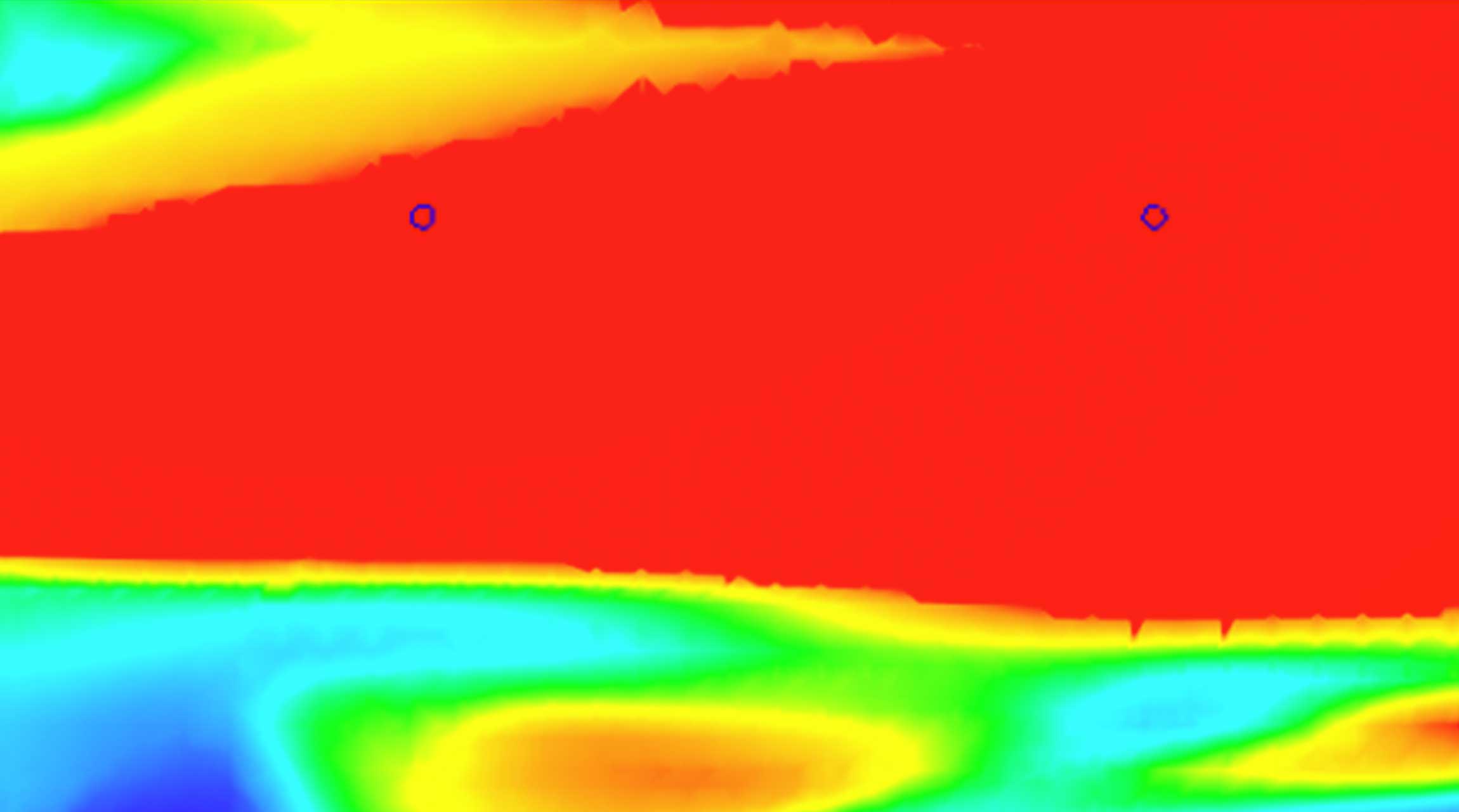
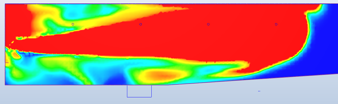
Section through the deep end of a 25m pool tank, local to an inlet. Red represents a high concentration of dye and blue shows undyed water. This emphasises that when a dye test is viewed from the pool surrounds, much of what is going on below the surface is unknown.
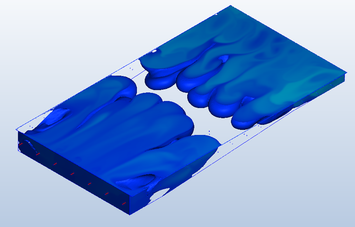
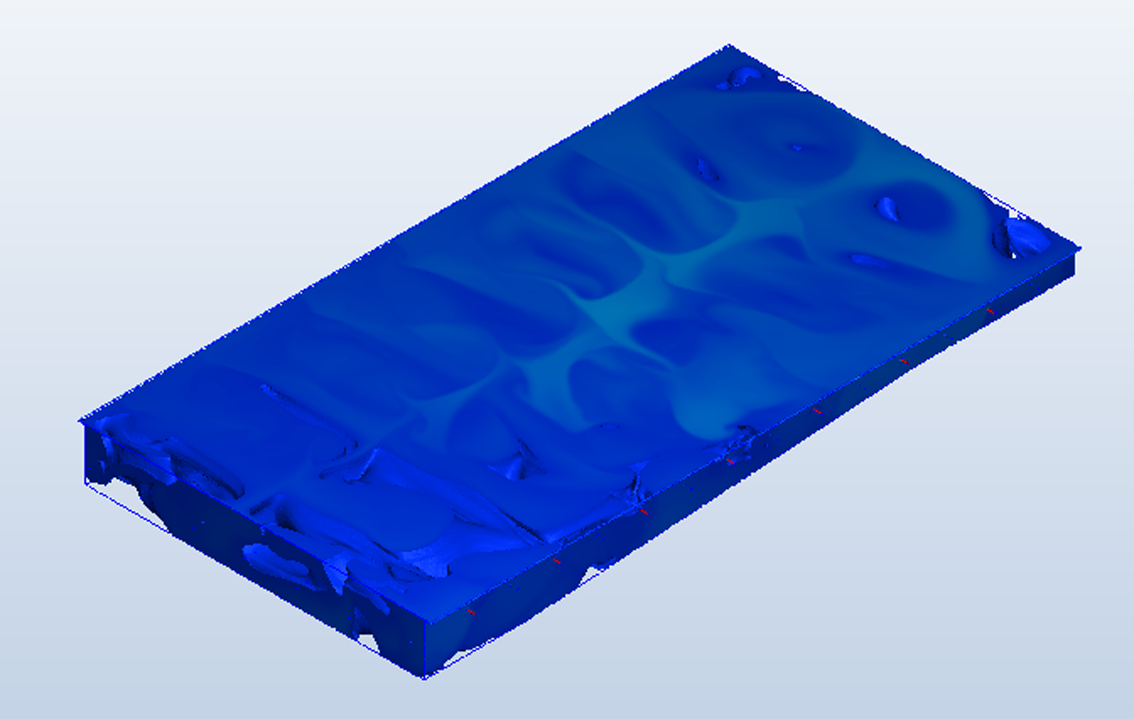
Snapshots after 15 minutes of a dye test on a 25m pool with end wall inlets (left) and side wall inlet (right). This shows that full dye coverage is achieved more quickly with the side wall arrangement.
Particle tracking in a 25m pool. Showing routes taken from the inlets to the transfer channel. (Using traces feature with velocity illustrated by colours)
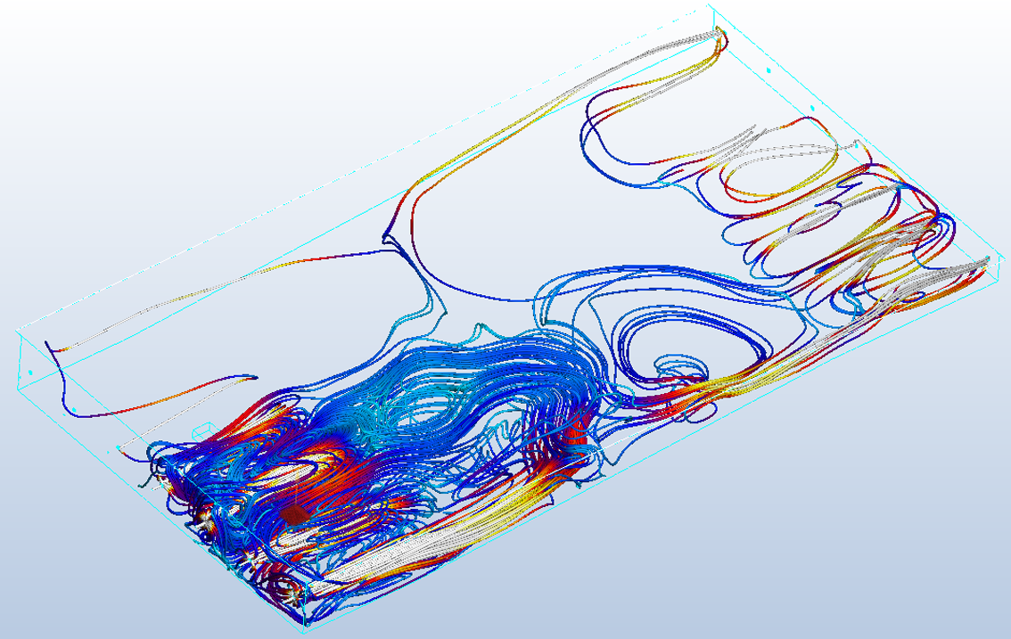
Particle tracking through a single base outlet (Using traces feature with velocity illustrated by colours – note there are a few different colour options available)
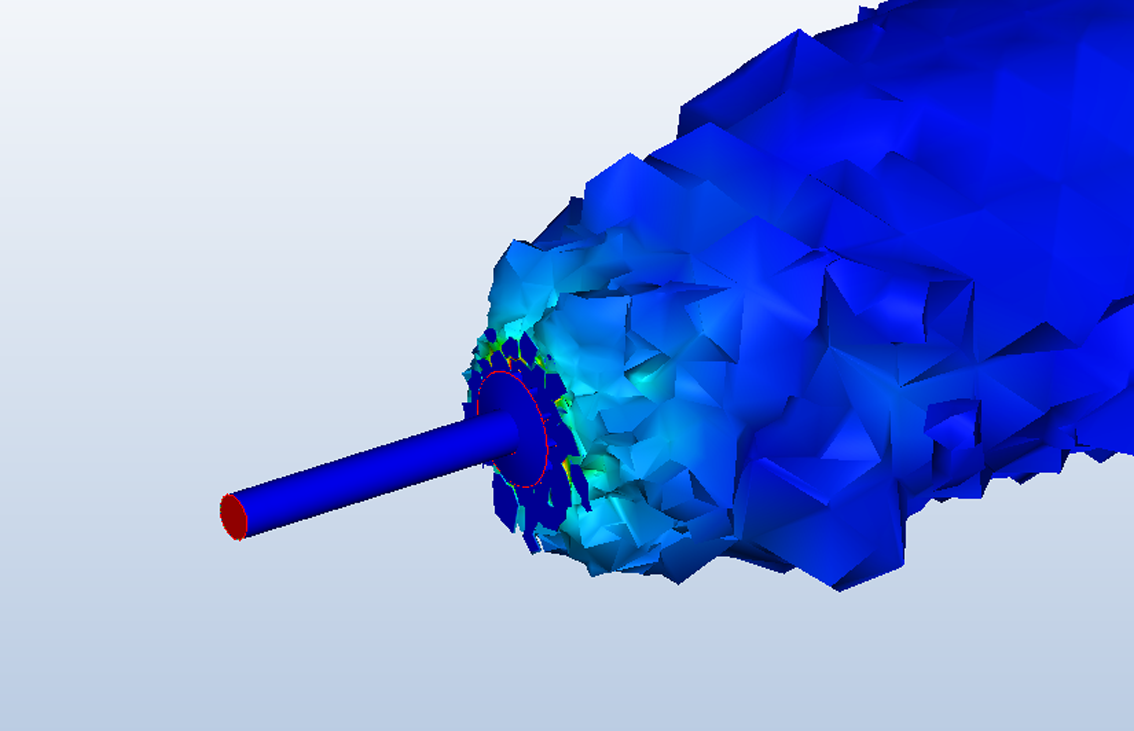
Flow profile at the inlet, showing similar shape to the image from the real pool dye test. (Iso volume showing scalar (dye) profile and colouring by dye concentration (velocity can also be used as the colour here)).